
UML includes a set of graphic notation techniques to create visual models of software-intensive systems.
The Unified Modeling Language (UML) is used to specify, visualize, modify, construct and document the artifacts of an object-oriented software intensive system under development. UML offers a standard way to visualize a system's architectural blueprints, including elements such as:
- actors
- business processes
- (logical) components
- activities
- programming language statements
- database schemas, and
- reusable software components.
UML diagrams represent two different views of a system model:
- Static (or structural) view: Emphasizes the static structure of the system using objects, attributes, operations and relationships. The structural view includes class diagrams and composite structure diagrams.
- Dynamic (or behavioral) view: Emphasizes the dynamic behaviour of the system by showing collaborations among objects and changes to the internal states of objects. This view includes sequence diagrams, activity diagrams and state machine diagrams.
Diagrams overview
UML 2.2 has 14 types of diagrams divided into two categories.[10] Seven diagram types represent structural information, and the other seven represent general types ofbehavior, including four that represent different aspects of interactions. These diagrams can be categorized hierarchically as shown in the following class diagram: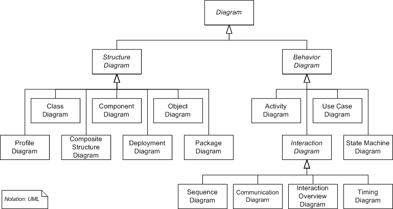
UML does not restrict UML element types to a certain diagram type. In general, every UML element may appear on almost all types of diagrams; this flexibility has been partially restricted in UML 2.0. UML profiles may define additional diagram types or extend existing diagrams with additional notations.
In keeping with the tradition of engineering drawings, a comment or note explaining usage, constraint, or intent is allowed in a UML diagram.
Structure diagrams
Structure diagrams emphasize what things must be in the system being modeled:
- Class diagram: the class diagrams describes the structure of a system by showing the system's classes, their attributes, and the relationships among the classes.
- Component diagram: depicts how a software system is split up into components and shows the dependencies among these components.
- Composite structure diagram: describes the internal structure of a class and the collaborations that this structure makes possible.
- Deployment diagram: serves to model the hardware used in system implementations, and the execution environments and artifacts deployed on the hardware.
- Object diagram: shows a complete or partial view of the structure of a modeled system at a specific time.
- Package diagram: depicts how a system is split up into logical groupings by showing the dependencies among these groupings.
- Profile diagram: operates at the metamodel level to show stereotypes as classes with the <
> stereotype, and profiles as packages with the < > stereotype. The extension relation (solid line with closed, filled arrowhead) indicates what metamodel element a given stereotype is extending.
 |  |  | |
 |
Since structure diagrams represent the structure they are used extensively in documenting the architecture of software systems.
Behavior diagrams
Behavior diagrams emphasize what must happen in the system being modeled:
- Activity diagram: represents the business and operational step-by-step workflows of components in a system. An activity diagram shows the overall flow of control.
- State machine diagram: standardized notation to describe many systems, from computer programs to business processes.
- Use case diagram: shows the functionality provided by a system in terms of actors, their goals represented as use cases, and any dependencies among those use cases.
 |  |  |
Since behavior diagrams illustrate the behaviour of a system, they are used extensively to describe the functionality of software systems.
Interaction diagrams
Interaction diagrams, a subset of behaviour diagrams, emphasize the flow of control and data among the things in the system being modeled:
- Communication diagram: shows the interactions between objects or parts in terms of sequenced messages. They represent a combination of information taken from Class, Sequence, and Use Case Diagrams describing both the static structure and dynamic behavior of a system.
- Interaction overview diagram: are a type of activity diagram in which the nodes represent interaction diagrams.
- Sequence diagram: shows how objects communicate with each other in terms of a sequence of messages. Also indicates the lifespans of objects relative to those messages.
- Timing diagrams: are a specific type of interaction diagram, where the focus is on timing constraints.
 |  |  |
Page Content Source: Wikipedia